2. Device description
1. Technical data
1.1 Temperature limitations
| Operating Temperature: | 0℃~50℃ |
| Storage Temperature: | -40℃~70℃ |
| Operating Humidity: | 10%~90% non-condensing |
| Storage Humidity: | 5%~90% non-condensing |
1.2 Dimensions and Weight:
| Main module: | 30*85*230 [mm], 358 [g] |
| Energy Meter module: | 30*85*93 [mm], 256 [g] |
1.3 Voltage Supply:
| Power supply: | 5-36 VDC |
| Idle electrical consumption main unit: | 2.5W (24V) |
| Idle electrical consumption main unit + 1x Energy Meter unit: | 3.0W (24V) |
| Max electrical consumption: | 20W |
| Power voltage limitation for the Main unit (L+, M) | -40V to +38V |
2. Connectors
2.1 Push-in CAGE CLAMP WAGO requirements
For all units in our device we use WAGO cage clamp connectors. Please ensure that your wires meet the following requirements:
Wire Gauge: Use wires within the recommended gauge range for optimal connection.
Insulation Type: Choose wires with insulation compatible with the connector’s clamping mechanism and operating conditions.
Stripping Length: Strip wire ends to the appropriate length for secure clamping.
Wire Preparation: Straighten and clean wire ends before insertion to ensure proper contact.
Refer to the table below for detailed specifications:
| Solid conductor: | 0.14 … 1.5 mm² / 28 … 16 AWG |
| Fine-stranded conductor: | 0.14 … 1.5 mm² / 26 … 14 AWG |
| Fine-stranded conductor; with insulated ferrule: | 0.25 … 0.75 mm² |
| Fine-stranded conductor; with uninsulated ferrule: | 0.25 … 1.5 mm² |
| Strip length: | 8 … 9 mm / 0.31 … 0.35 inches |
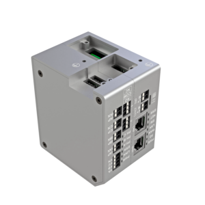
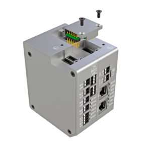
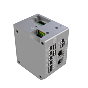
2.2 New units connection
To integrate a new measurement unit simply follow the procedure demonstrated on the pictures bellow to assemble an interconnection bridge between the units.
⚠️ Safety Notice: Before adding a new unit, ensure that all wires are disconnected or have no voltage. Failure to do so may result in electrical hazards or damage to the device.
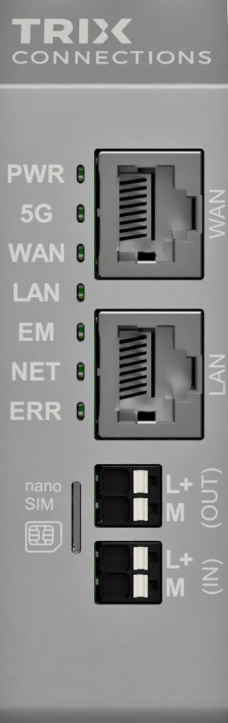
3. Front Panel Interface