-
Basics
- 1. Quick Start Guide
- 2. Device description
- 3. Safety information
- 4. Restart & reset device
- 5. Passwords
- 6. VXLAN
- 7. Firewall zones and rules
- 8. Static IP / Dynamic IP
- 9. LAN / WAN configuration
- 10. DHCP
- 11. Port forwarding
- 12. OPC UA
- 13. MQTT
- 14. Backup & Load Configuration
- 15. Flash new firmware
- 16. WWAN configuration
- 17. Watchcat
- 18. Modem
- 19. IO unit
- Show Remaining Articles ( 4 ) Collapse Articles
19. IO unit
The I/O unit offers six configurable inputs/outputs, providing flexibility and versatility for a range of industrial applications.
Key Specifications:
- Up to 8 I/O units can be installed in sequence without external power. In this setup, they operate in “logic” mode, limiting the maximum output current to 0.02A per channel.
- With external power, a maximum of 24 I/O units can be installed in sequence.
- The unit complies with the IP31 protection standard, ensuring basic protection against dust and low-level water exposure.
Operating Modes:
- Digital Input (DI): Inputs can be configured to handle signals up to 30VDC. The I/O threshold and signal filters can be adjusted through the web UI, with future updates allowing for faster communication without hardware modifications.
- Digital Output (DO): Two options: 24V 0.02A output and 24VDC 0.5A output with external power. DO pins operate in “Push-Pull” mode (logic “1” = 24VDC, logic “0” = 0VDC).
- Analog Input (AI): Configurable to accept either 4-20mA or 0-10V signals via the web UI.
1. Technical Data
1.1 Temperature Range:
| Operating Temperature: | 0℃ to 50℃ |
| Storage Temperature: | -40℃ to 70℃ |
| Operating Humidity: | 10% to 90% (non-condensing) |
| Storage Humidity: | 5% to 90% (non-condensing) |
1.2 Dimensions and Weight:
| Module Size: | 30 x 85 x 93 mm |
| Weight: | 256 g |
1.3 Voltage Supply:
| Power Supply: | 5-36 VDC |
| Idle Consumption (Main Unit): | 2.5W (24V) |
| Idle Consumption (Main Unit + 1x Energy Meter): | 3.0W (24V) |
| Max Power Consumption: | 20W |
| Voltage Limit (Main Unit): | -40V to +38V |
1.4 General Limitations:
| Max Units Without External Power: | 8 (Max 0.02A per output channel) |
| Max Units With External Power: | 24 |
2. Connectors
2.1 Push-in CAGE CLAMP (WAGO) Requirements:
We use WAGO cage clamp connectors for all units. Ensure your wires meet the following specifications for optimal performance:
- Wire Gauge: Ensure wire gauge is within the recommended range.
- Insulation Type: Use wires with compatible insulation for the connector’s clamping mechanism and environment.
- Stripping Length: Strip wire ends to the correct length for secure clamping.
- Wire Preparation: Straighten and clean wire ends before insertion for proper contact.
Refer to the table below for more details:
| Solid Conductor: | 0.14 – 1.5 mm² / 28 – 16 AWG |
| Fine-Stranded Conductor: | 0.14 – 1.5 mm² / 26 – 14 AWG |
| Fine-Stranded w/ Insulated Ferrule: | 0.25 – 0.75 mm² |
| Fine-Stranded w/ Uninsulated Ferrule: | 0.25 – 1.5 mm² |
| Strip Length: | 8 – 9 mm / 0.31 – 0.35 inches |
2.2 Connecting New Units:
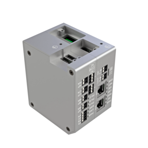
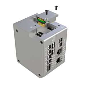
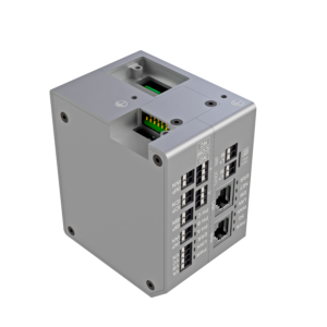
To connect a new measurement unit, follow the procedure shown in the images below to assemble the interconnection bridge.
⚠️ Safety Notice: Ensure all wires are disconnected or voltage-free before adding new units to prevent electrical hazards or device damage.


3. Front Panel Interface
| LED | State | Meaning |
|---|---|---|
| PWR | Light | The device is ready. |
| Blinking | The device is booting up. | |
| No light | There is no power. Please check the power source. | |
| LINK | ||
| Blinking | Indicates communication with the main unit. | |
| No light | There is no communication with the main unit. | |
| ERR | Light | An error has occurred, or the configuration process is in progress. |
| No light | No issues have been detected. | |
| EXT | Light | External power connected. |
| No light | External power is not connected. | |
| 1 | Light | There is logic “1” on the IO pin. |
| No light | There is logic “0” on the IO pin | |
| 2 | Light | There is logic “1” on the IO pin. |
| No light | There is logic “0” on the IO pin | |
| 3 | Light | There is logic “1” on the IO pin. |
| No light | There is logic “0” on the IO pin | |
| 4 | Light | There is logic “1” on the IO pin. |
| No light | There is logic “0” on the IO pin | |
| 5 | Light | There is logic “1” on the IO pin. |
| No light | There is logic “0” on the IO pin | |
| 6 | Light | There is logic “1” on the IO pin. |
| No light | There is logic “0” on the IO pin |
4. Unit Protection
All pins in every configuration are protected against high voltage, high current, and reverse polarity. However, it’s important to note that the M and L+ power pins, as well as the I/O pins on the I/O unit, are not galvanically isolated.
Power Modes:
- Logic Mode (without external power):
- Maximum total power output (L+, M, and I/O): 150mA
- Maximum I/O output per channel: 20mA
- Power Mode (with external power):
- Maximum total power output (L+, M, and I/O): 3.5A
- Maximum I/O output per channel: 0.5A
Automatic Protection Features:
- Short-circuit or excess current on L+ and M: The unit will automatically shut down until the issue is resolved.
- Excess current on I/O pins: The affected I/O pin will be automatically disabled until the issue is resolved.
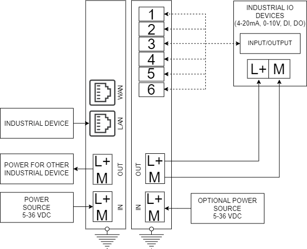
5. Schematics connection for 5G-IIoT + IO unit

