5G-IIoT Gateway Manual
1. Quick Start Guide
Welcome to the online Quick Start Guide for the 5G-IIoT Gateway. Here you will find an overview of the hardware installation instructions, device specifications, essential safety information, and an initial setup guide. Familiarizing yourself with this guide before using the device is advised to ensure a seamless setup process.
1. Safety information
Before proceeding to use the device, it’s essential to review the safety information provided in the Safety information section of the user manual. This section outlines important guidelines and precautions to ensure your safety and the proper functioning of the device. Taking a moment to familiarize yourself with this information will help prevent accidents and ensure a smooth user experience.
2. General information
Technical information about the device can be found in the Device description page.
| Power supply: | 5-36 VDC |
| Idle electrical consumption Main unit: | 2.5W(24V) |
| Idle electrical consumption Main unit + 1x Energy Meter unit: | 3.0W(24V) |
| Max electrical consumption: | 20W |
3. Hardware setup
3.1 Connect the modules
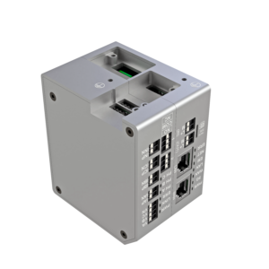
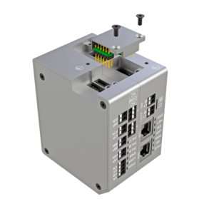
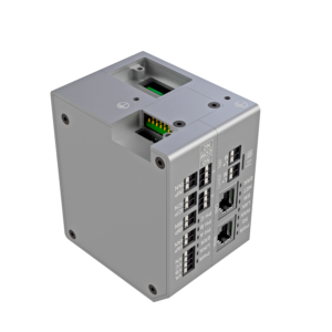
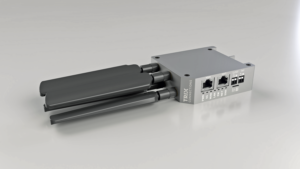
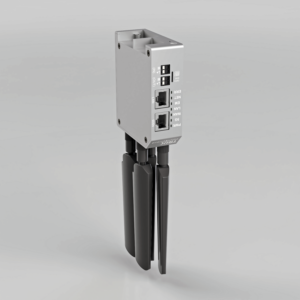
First, connect any required hardware modules via the enclosed bridge connector part, as shown in the following images.
3.2 Power the device
Connect the device to a 5-36 VDC power source via the IN power terminals. The OUT terminals can be used to power multiple devices in a chain by connecting the powered device’s OUT terminals to an unpowered unit’s IN terminal.
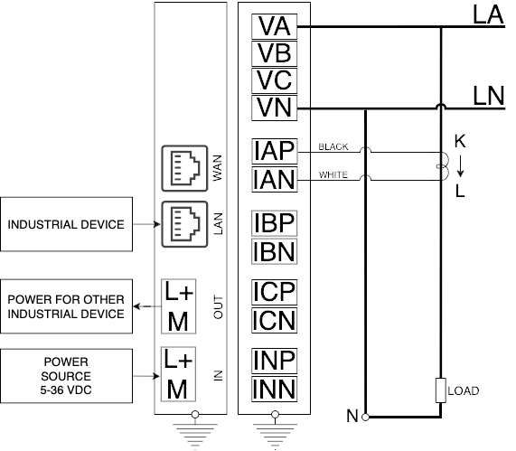
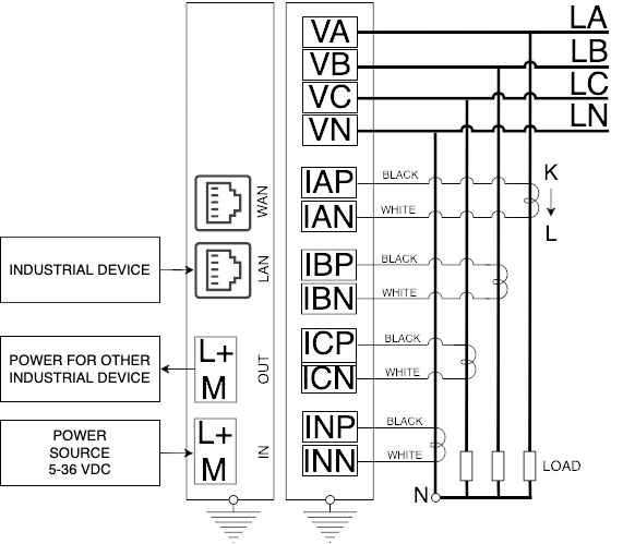
3.3 Connect the sensors
When using the Energy Meter unit, connect it using one of the following schemes.


4. Connecting to the device
Connect the device to your computer with an Ethernet cable via the LAN port.
4.1 Troubleshooting (Windows)
4.1.1 Enabling your Network Adapter
Make sure your network adapter is enabled:
1. Open the “Control Panel” from the Start menu.
2. In the Control Panel, navigate to “Network and Internet” or “Network and Sharing Center.”
3. Click on “Network and Sharing Center.”
4. In the left pane, select “Change adapter settings.”
5. Here, you’ll see a list of network connections. Right-click on the disabled network adapter you want to enable.
6. Choose “Enable” from the context menu. Alternatively, you can also click on the “Enable” option in the toolbar.
7. Once enabled, the network adapter icon will change to indicate an active connection.
4.1.2 Enable automatic IP address acquisition
To configure a Windows computer to obtain an IP address and DNS server address automatically, follow these steps:
1. Open the “Control Panel” from the Start menu.
2. In the Control Panel, navigate to “Network and Internet” or “Network and Sharing Center.”
3. In the left pane, select “Change adapter settings.”
4. Right-click on the network connection you want to configure and select “Properties” from the context menu.
5. In the Properties window, scroll down and select “Internet Protocol Version 4 (TCP/IPv4)” and then click on the “Properties” button.
6. In the IPv4 Properties window, ensure that the options “Obtain an IP address automatically” and “Obtain DNS server address automatically” are selected.
7. Click “OK” to save the changes and close the windows.
8. You may need to restart your computer or reconnect to the network for the changes to take effect.
Your Windows computer will now automatically obtain an IP address and DNS server address when connected to the network.
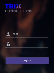
5. Log into the device
To access the web user interface (UI), enter the default LAN IP address http://192.168.0.1 into the URL field of your preferred browser. This action will direct you to the login page of the web UI. Utilize the login credentials found on the device’s information label to log in and access the UI.
6. Next steps
Explore the remainder of the documentation to learn how to use the web UI to configure your device, including instructions on changing your default password found in the passwords section.
2. Device description
The 5G-IIoT gateway is the universal platform to connect and measure data from industrial systems through 5G. The device comprises the Main unit, which can operate independently or in conjunction with other modules.
1. Technical data
1.1 Temperature limitations
| Operating Temperature: | 0℃~50℃ |
| Storage Temperature: | -40℃~70℃ |
| Operating Humidity: | 10%~90% non-condensing |
| Storage Humidity: | 5%~90% non-condensing |
1.2 Dimensions and Weight:
| Main module: | 30*85*230 [mm], 358 [g] |
| Energy Meter module: | 30*85*93 [mm], 256 [g] |
1.3 Voltage Supply:
| Power supply: | 5-36 VDC |
| Idle electrical consumption main unit: | 2.5W (24V) |
| Idle electrical consumption main unit + 1x Energy Meter unit: | 3.0W (24V) |
| Max electrical consumption: | 20W |
| Power voltage limitation for the Main unit (L+, M) | -40V to +38V |
2. Connectors
2.1 Push-in CAGE CLAMP WAGO requirements
For all units in our device we use WAGO cage clamp connectors. Please ensure that your wires meet the following requirements:
Wire Gauge: Use wires within the recommended gauge range for optimal connection.
Insulation Type: Choose wires with insulation compatible with the connector’s clamping mechanism and operating conditions.
Stripping Length: Strip wire ends to the appropriate length for secure clamping.
Wire Preparation: Straighten and clean wire ends before insertion to ensure proper contact.
Refer to the table below for detailed specifications:
| Solid conductor: | 0.14 … 1.5 mm² / 28 … 16 AWG |
| Fine-stranded conductor: | 0.14 … 1.5 mm² / 26 … 14 AWG |
| Fine-stranded conductor; with insulated ferrule: | 0.25 … 0.75 mm² |
| Fine-stranded conductor; with uninsulated ferrule: | 0.25 … 1.5 mm² |
| Strip length: | 8 … 9 mm / 0.31 … 0.35 inches |
2.2 New units connection
To integrate a new measurement unit simply follow the procedure demonstrated on the pictures bellow to assemble an interconnection bridge between the units.
⚠️ Safety Notice: Before adding a new unit, ensure that all wires are disconnected or have no voltage. Failure to do so may result in electrical hazards or damage to the device.
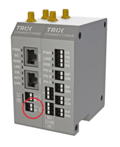
3. Front Panel Interface
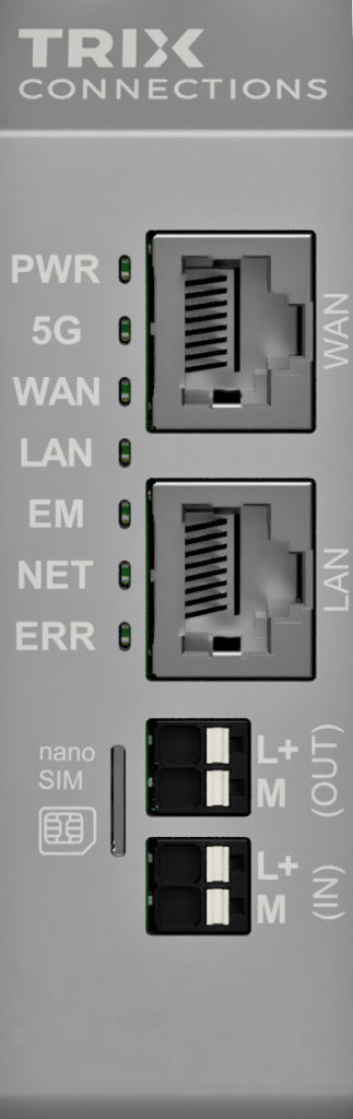
| LED | State | Meaning |
|---|---|---|
| PWR | Light | The device is ready. |
| Blinking | The device is booting up. | |
| No light | There is no power. Please check the power source. | |
| 5G | Light | The modem is on and attempting to connect. |
| Blinking | The modem is operational and the network connection is good. | |
| No light | There is no modem or it is turned off. | |
| WAN | Blinking | Communication is okay. |
| No light | There is no communication. | |
| LAN | Blinking | Communication is okay. |
| No light | There is no communication. | |
| EM | Light | The units have been initialized. |
| Blinking | There is some problem with the unit, possibly due to incorrect configuration. | |
| No light | Initialization of extension modules is in progress. | |
| NET | Light | Indicates communication with units. |
| ERR | Light | An error has occurred, or the configuration process is in progress. |
| No light | No issues have been detected. |
3. Safety information
General Safety Rules:
-
Read this manual
Before working with this device, carefully read this manual and adhere to all safety advice provided.
-
Compliance with laws and regulations
Use the router in compliance with national and international laws, as well as any special or additional restrictions regulating its use in various applications and environments. It is imperative to adhere to legal requirements and regulations to ensure lawful and safe operation of the router.
-
Avoid unauthorised modifications and accessories
Unauthorised modification of the device or use of accessories that have not been approved can result in injury, termination of warranty, or damage to the device. Always use approved accessories and refrain from modifying the device without proper authorisation to ensure safety and compliance with warranty terms.
-
Personal qualifications
All wiring must be performed exclusively by electrical specialists possessing the required level of knowledge and appropriate qualifications as stipulated by local legislation.
-
Do not open device
Under no circumstances should the device be opened. Doing so may expose individuals to hazardous components and increase the risk of electric shock. If the device is defective, do not attempt to repair it. Instead, replace it with a new module.

-
Do not work on device while energised
All power sources to the device should be turned off before performing any work on the hardware.
-
Install the device in appropriate housing
This device must be installed inside an appropriate housing, electrical cabinet, or electrical operation room. Outdoor use is prohibited. Ensure, that the Ambient Conditions specified in Device description -> 1.0 Temperature limitations are always met.

-
Provide functional grounding
This device must always be grounded. Connect the grounding cable via screw with clamping washer to the grounding terminal located on the lower side of the metal casing. If expansion modules are used, each of them must be grounded individually.
-
Use end sleeves for stranded wires
End sleeves are strongly recommended for all non-solid connection cables. Please check the wire requirements in Device description -> 2. Connectors
-
Avoid Electrostatic discharge
The device may be damaged by electrostatic discharge when touched. When handling the device, make sure that everything that comes into contact with the device is grounded.
-
Strictly follow connection diagrams
To ensure safe and correct operation, always pay special attention to connection diagrams.
-
Do not exceed defined supply voltage
Exceeding the specified voltage may result in damage to the device, risk of electric shock, or fire hazard. Always adhere to the recommended voltage limits outlined in the Device description -> 1.2 Voltage Suply.
-
Do not use in explosive environments
This device is not intended for use in potentially explosive atmospheres. Avoid using the device in environments where flammable gases, vapours, or dust may be present, as this could lead to the risk of fire or explosion.
-
Caution when using near personal medical devices
Exercise heightened caution when using the router in proximity to personal medical devices, such as cardiac pacemakers or hearing aids. Electromagnetic interference from the router may affect the functionality of these devices.
Additional Safety Rules for 3-phase Power Measurement Module:
-
Protect the voltage measurement connection cables
The voltage measurement connection cables must be protected against short-circuit. Take into consideration the cross-section of the cables.
-
Never operate the current transformers with open load
Although the provided current transformers are equipped with protective diodes limiting output voltage, they should never be attached to a live wire without being properly connected to the power measurement module.
4. Restart & reset device
Restarting the device
It might be needed to restart the device to apply some changes; in such cases, there are two options:
- Log into the router interface, and under System -> Reboot, press the reboot button.
- Disconnect the router from its power supply for five seconds and plug it back in.
Resetting the device to factory settings
To reset the device to factory settings, perform the following steps:
1. Restart the device, either in the web interface or by disconnecting and connecting the power supply.
2. While the device is booting, as indicated by the blinking PWR LED, rotate the device so that the side with the printed information (printed side) faces downward.
3. Once the device finishes booting, indicated by the continuous illumination of the PWR LED, a beeping sound should follow after approximately three seconds to indicate the start of the reset sequence.
4. Following the beep sound, promptly rotate the device so that the side with the antennas connections (antenna side) faces downward. Another beep should occur approximately three seconds later.
5. After the beep, promptly return the device back down to its original position with the printed side facing downward and wait for another beep.
6. After the beep, promptly place the antenna side of the device facing downward. At this point, the device will reset, indicated by a series of beeps and the turning on of the EW, NET, and ERR LEDs.
The horizontal rotation of the device does not matter, but the indicated side must face down. It does not have to be perfectly horizontal; there is some leniency with the down angle. The rotations must occur quickly after the indication sounds (2~3 s). If the indication sound does not occur within ten seconds, the process has to be started again from the beginning. Note that a successful reboot resets the password back to the default.
5. Passwords
The password is used to log into the router interface.
Default password
The default password is set by the manufacturer and can be seen printed on the outside of the gateway device. This is the password used when first connecting to the device or after a factory reset.
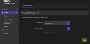
Changing the password
For security reasons it is recommended to change the default password, this can by done with the following steps:
- Navigate to System -> Administration -> Router Password
- Choose a new secure password
- Save your changes using the Save button
6. VXLAN
VXLAN configuration
Here we describe how to set up VXLAN with access to the internet via 5G. VXLAN allows for the connection of separate LANs into one virtual LAN; as such, it is important that the connected devices have different LAN addresses. The subsequent section will guide you through establishing connections between two devices, followed by instructions for connecting additional devices to the VXLAN.
Connecting two devices
The steps are identical for both end devices; only the Remote and Local IP addresses are swapped.
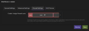
1. Navigate to Network -> Interfaces -> Interfaces.
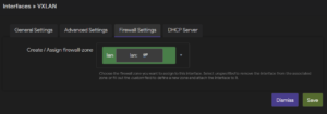
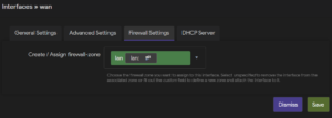
2. Under wwan -> Edit -> Firewall Settings, assign firewall-zone to wan and click Save.
3. Add the new VXLAN interface by using the Add new interface button and selecting the VXLAN (or VXLANv6) protocol.
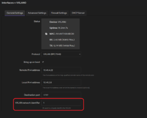
4. Now, in the VXLAN interface, under General settings, set the Remote and Local IP (address in 5G network)
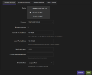
5. Under Firewall Settings, set the firewall-zone to lan and click Save & Apply.
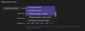
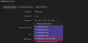
6. Now add the VXLAN to the bridge device. Under Network -> Interfaces -> Devices, configure the br-lan device. In General device options -> Bridge ports, add “VXLAN0” (or “vxlan6”) and save your settings.
7. Click Save & Apply at the bottom of the page.
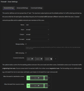
8. Navigate to Network -> Firewall -> General Settings -> Zones and edit zone wan.
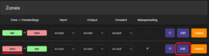
9. Under General Settings, set Input, Output, and Forward to accept, and “Allow forward to destination zones” to lan. Save your settings and click Save & Apply at the bottom of the page.
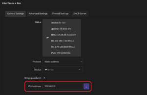
10. Make sure both devices have different LAN addresses. If not change them under Network -> Interfaces -> Interfaces -> lan -> Edit
11. To enable your changes, reboot your device under System -> Reboot.
Adding more devices to the network
We recommend using a star topology to connect additional 5G-IIoT Gateways to the network, because there is a nontrivial communication delay on jumps between individual LANs. For this, it is required to designate one device as a hub, which connects to all other devices. Preferably, this would be the device connected to the main/control block in the production to minimize the communication between non-hub devices. The following steps describe how to connect additional devices to the VXLAN:
1. Start by connecting two devices by following the instructions from the previous section.
2. When connecting more than two devices, it is required to set the “VXLAN network identifier.” Find your created VXLAN interface under Network -> Interfaces -> Interfaces and click the Edit button. Set the same numeric “VXLAN network identifier” on both the hub and connected device.
3. Now, on the hub device, create a second VXLAN interface, this time using the remote address of the device you want to connect and setting a new unique “VXLAN network identifier.” Following that, add the new interface to the bridge device. If you are unsure how to do it, see steps 3. – 7. in the section on connecting two devices.
4. Save & Apply your changes.
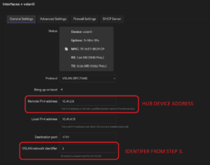
5. Set up the new device according to the steps from the previous section. This time set the remote address as the hub device address and the “VXLAN network identifier” to the ID for the second VXLAN interface (step 3.).
6. Make sure all connected devices have unique LAN addresses. If not change them under Network -> Interfaces -> Interfaces -> lan -> Edit
7. Firewall zones and rules
Zones
The firewall can group interfaces into zones for which rules, forwards, and redirects can be set, allowing for more logical traffic filtering. Any interface can be grouped into zones, but generally, there are zones collecting LAN and WAN interfaces.
Configuring zones
Zones can be configured in the router interface section Network -> Firewall -> General Settings.
The Zones section shows current zones and forwarding rules, and a new zone can be added using the Add button.
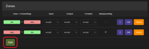
When creating or editing a zone, default properties, such as Input, Output, and Forward, can be set:
- Input: Policy for incoming traffic.
- Output: Policy for outgoing traffic.
- Forward: Set policy for traffic between the networks within the zone.
Which networks are assigned to the zone can be set under Covered networks.

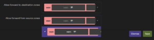
Forwarding between zones is set by selecting the zone to which traffic can be forwarded from the current zone in Allow forward to destination zones, and selecting the zone from which forwarded traffic is accepted in Allow forward from source zones. The forwarding rule is unidirectional; e.g., a forward from lan to wan does not imply permission to forward from wan to lan as well.
Adding interfaces to zones
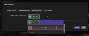
Individual interfaces (Network -> Interfaces -> Interfaces) can be assigned to a zone when creating or editing an interface under the tab Firewall Settings.
Firewall – Traffic Rules
Firewall (traffic) rules are used to control traffic flow in a firewall. They allow us to specify packets based on criteria such as protocol, zones, IP addresses, and ports and apply actions (accept, reject, drop, etc). Firewall rules control how the firewalls prevent malicious programs and unauthorized traffic from compromising your network.
Traffic rules configuration
The firewall rules can be set in the interface under Network -> Firewall -> Traffic Rules

New rules can be added by using the Add button at the bottom of the page. When creating new rules it is recommended to use a naming scheme, for easier maintenance and debugging. New rules can filter packets by:
- Protocol
- Source
- Zone
- IP address
- Port
- Destination
- Zone
- IP address
- Port
In the “Action” field we set the action which is applied to the filtered packets. These actions can be:
- Accept
- Reject
- Drop
- Don’t track
- Assign conntrack helper
- Apply firewall mark
- XOR firewall mark
- DSCP classification
8. Static IP / Dynamic IP
The Internet Protocol (IP) address is a unique number assigned to every device on a network. It can either be set manually (static IP) or assigned dynamically via the DHCP (Dynamic IP).
Static IP
A static IP address can be set up for interfaces (Network -> Interfaces) by selecting the “Static Address” protocol when creating or editing an interface.
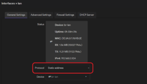
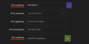
Then, the specific IPv4 or IPv6 addresses can be set.
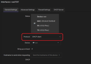
Dynamic IP
A dynamic IP address can be set up for interfaces (Network -> Interfaces) by selecting the “DHCP client” protocol when creating or editing an interface. With this, the interface will lease an IP address from a connected DHCP server.
9. LAN / WAN configuration
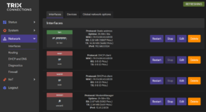
The WAN and LAN interfaces can be configured under Network -> Interfaces.
Local area network (LAN)
A LAN is a network infrastructure that interconnects computing devices within a confined geographical area, typically within a building or campus. It facilitates communication and resource sharing among connected devices, enabling efficient data exchange, file sharing, and centralized access to services such as printing and internet connectivity.
By default, in the gateway, the four LAN ports are connected by a bridge device and set up under the lan interface. Only port “lan1” is physically accessible from the main unit; a hardware extension is required to access the remaining ports. By default, the interface is set to the static address 192.168.0.1 and is in a separate firewall zone from the WAN, though forwards from the LAN zone to the WAN zone are allowed.
Wide area network (WAN)
A WAN (Wide Area Network) is a network infrastructure that spans a large geographical area, connecting multiple LANs and other networks across different locations, such as cities, countries, or continents. It facilitates long-distance communication and data exchange between geographically dispersed computing devices.
The WAN port is set up in the wan (IPv4) and wan6 (IPv6) interfaces as DHCP clients.
Configuring ports to WAN/LAN
Warning: Before re-configuring ports, ensure you will be able to access your device throughout and after the reconfiguration process.
Example: Change WAN port to LAN
If two LAN ports are required instead of a LAN and WAN port, it is possible to add the WAN port to the LAN network. To do this, configure the bridge device under Network -> Interfaces -> Devices by adding the wan port to the bridge ports.
Next move the wan interface from the WAN firewall zone to the LAN zone. By editing the wan zone under Network -> Interfaces-> Interfaces, and under Firewall Settings assign zone lan. If a different Protocol is required for the interface (for example a static address) it can be changed under General Settings.
Example: Change LAN port to WAN
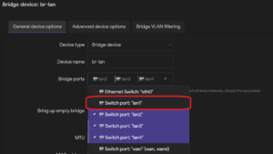
To change a LAN port to WAN, remove the chosen LAN port from the Bridge device under Network -> Interfaces -> Devices; in this example, we choose lan1. Note that only lan1 has a hardware connection on the main unit. A hardware extension is required to access lan2, lan3, and lan4.
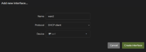
Next, under Network -> Interfaces-> Interfaces, add a new interface, select the “DHCP client” Protocol, and as the Device, choose your selected LAN port. Then, assign the new interface to the firewall zone wan in the interface under Firewall Settings.
10. DHCP
The Dynamic Host Configuration Protocol (DHCP) automatically assigns IP addresses and related configuration information, such as the subnet mask and default gateway. The general DHCP settings are under Network -> DHCP and DNS -> General Settings.
Interface DHCP server
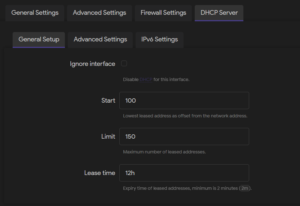
An interface with the “static address” protocol can be set up to serve DHCP requests. To do this, navigate to Network -> Interfaces and create or edit an interface. Ensure the protocol under General Settings is set to “Static address,” then under the interface tab DHCP Server, use the Set up DHCP Server button to configure the server for the interface. Under the tab General Setup, ensure the Ignore interface option is unchecked, and set the desired Start of the leased address range, Limit on the maximum number of leased addresses, and expiry Lease time.
Static lease
To ensure the DHCP always leases the same IP address, a static lease can be set up to assign a fixed IP address.
If it is required that the DHCP always assigns the same IP address to a connected device, a static lease has to be set up. This can be done in two ways: either the required static IP address is specified, or we only need the address to stay the same, but the specific address is not unspecified.
Specified
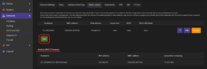
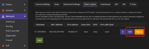
To set up a static lease with a specified IP address, navigate to Network -> DHCP and DNS -> Static Leases. Any active DHCP leases can be seen under the section Active DHCP leases, and new leases can be set via the Add button.
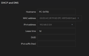
Then, the parameters of the static lease can be set:
Hostname: The symbolic name which is assigned to the requesting host.
MAC address: MAC address of the device to which the fixed IP address will be assigned.
IPv4 address: The fixed IP address which will be assigned.
Lease time: A non-standard host-specific lease time can be set, e.g., 12h, 3d or infinite.
Optionally, the DHCP Unique Identifier (DUID) and the IPv6 suffix (hex) can be set.
Unspecified
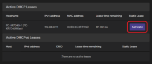
If the assigned IP address is irrelevant, an active DHCP lease can be set as static in Status -> Overview under the section Active DHCP Leases via the Set Static button.
Deleting or editing a static lease
Any active static lease can be changed or removed under Network -> DHCP and DNS -> Static Leases.
11. Port forwarding
Port forwarding allows remote computers on the Internet to connect to a specific computer or service within the private LAN.
Port forward configuration
Port forwards can be configured in the interface under Network -> Firewall -> Port Forwards. The Port Forwards section contains an overview of the current forwards and allows you to enable/disable, edit, or delete them.

Creating a new port forward
Use the Add button to create a new port forward.

12. OPC UA
An OPC UA (Open Platform Communications Unified Architecture) server implements the OPC UA protocol to provide data and services to OPC UA clients. It serves as a central hub for accessing real-time and historical data and executing operations within industrial automation systems. OPC UA servers facilitate secure and reliable communication between industrial devices, sensors, and software applications, enabling remote monitoring, control, and diagnostics. The 5G-IIoT gateway can host an OPC UA server to transmit sensor information.
Setting up an OPC UA server
To configure an 5G-IoT OPC UA server navigate to IIoT -> OPC UA, configure and Enable it, and press Save & Apply. Wait approximately 30 s for the server to start up.

Parameters
- Enable: Enable/Disable the OPC UA server.
- End point: Network address through which OPC UA clients can establish connections to OPC UA servers. Formatted as opc.tcp://SERVER_ADDRESS:SERVER_PORT/PATH
- SERVER_ADDRESS: Address of the server interface. Set it to the address of the interface (LAN, WAN, 5G) from which the server should be accessed, or set it to 0.0.0.0 to be accessible from all interfaces.
- SERVER_PORT: The communication port on which the OPC UA server is listening for incoming connections. OPC UA servers commonly use port 4840, although other ports can be configured.
- PATH: Optionally, the endpoint URL may include a path component, which further identifies the specific endpoint within the server.
- Root object name: Name of the object containing the sensor data. It can be set arbitrarily, but it’s recommended to choose it so it identifies the device when collecting data from multiple servers.
- EM count: Number of connected Energy Meter units.
Connecting to OPC UA from WAN/WWAN(5G)
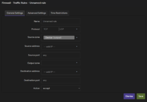
The OPC UA port can not be accessed from the WAN/WWAN(5G) by default. A new firewall rule must be created to allow access. To do this, navigate to the firewall rules under Network -> Firewall -> Traffic Rules and Add a new rule. Set the rule to accept traffic from the source zone WAN to the destination zone Device (input) and the desired OPC UA server port’s destination port, as shown in the following image.

To finish, save the new rule and push the Save & Apply button to apply your changes. For more information on traffic rules, check out the chapter on firewall rules.
OPC UA sensor data structure
Sensor data is transmitted under Objects/Root object name/EM_ID_x, where x identifies the Energy Meter unit in the range one to EM count. See the following image for an example.

| Online | True/False Indication if the main unit detects the connected unit. |
| Type | Type of the connected unit: 16 (0x10) indicates a EM unit. |
| Vrms | Measured root-mean-square (RMS) voltage in volts (V) for each phase. |
| Irms | Measured RMS current in ampere (A) for each phase. |
| Wat | Measured power in kW/h, for each phase. |
7. MQTT
All test results are published via MQTT. The MQTT publisher can be configured via the MQTT button on the main screen, which brings up the following configuration menu:

After configuring the MQTT publisher, confirm your settings by clicking the Apply button. If everything was successful, “MQTT client: ONLINE” should be visible in the bottom right corner of the main screen.
The MQTT messages are sent under TOPIC/DEVICE_IP, where topic is the topic name selected in the MQTT configuration, and DEVICE_IP is the IP address of the device being tested. Messages contain the measured data keyed by the test type; see the following image for an example message.
![]()
14. Backup & Load Configuration
Once the device configuration is finalized, creating a backup file to allow for simple reconfiguration in case of errors or to transfer the configuration to new devices is recommended.
Backup configuration
The device configuration can be backed up under System -> Backup / Flash Firmware by pressing the Generate archive button. A tar.gz archive file containing the current configuration files will be downloaded to your browser’s default download folder.
Load configuration
Before loading a new configuration, it is recommended to perform a factory reset, as otherwise, some custom files (certificates, scripts) may remain on the device. Please ensure you know the new password and LAN / WAN configuration so you can connect to the device after the new configuration has been applied. A new configuration can be loaded under System -> Backup / Flash Firmware by pressing the Upload archive button and selecting a tar.gz configuration archive file in the file browser. A confirmation window will pop up if a valid configuration file is selected; press Continue to reboot the device and finish loading the new configuration. The selection of an invalid configuration file will be signified by an error message at the top of the page.

15. Flash new firmware
The following steps describe how a new firmware image file can be flashed on a device.
Flashing a new image
It is strongly recommended to use a LAN connection when flashing new firmware. As the firewall configuration might change during the flashing process, and a wireless connection might be lost.
New device firmware can be flashed under System -> Backup / Flash Firmware by pressing the Flash image button.

This will open up a prompt for uploading the new image file. After the image file has been uploaded, a new window will show the checksum and file size listed. It is recommended that the checksum and file size be compared with the original file to ensure data integrity.

If the previous settings should be retained, check the Keep settings and retain the current configuration box.
Only keep settings if configuration needs to be retained
Checking the Keep settings and retain the current configuration check-box will retain the current settings (Firewall, OPC UA, VXLAN, MQTT, etc…). If a clean install is desired this check-box should not be checked.
Next, check the Force upgrade checkbox to override the previous flashed image and click the Continue button to finalize the process.
16. WWAN configuration
The wireless wide area network (WWAN) interfaces can be configured under Network -> Interfaces.

Interface configuration
Either edit the default WWAN interface or create a new one via the add interface button. Select the ModemManager protocol and select an available modem device. The following parameters can be set:
- Access point name (APN). The interface uses either the default APN of the SIM or it can be manually configured. If the manually configured APN does not work, the device will revert to using the SIM APN.
- PIN. If the SIM is locked, the PIN code must be set.
- Authentication type. The authentication method used. Can be set as PAP, CHAP, or both (PAP/CHAP)
- Signal refresh rate. Refresh rate in seconds.

17. Watchcat
Watchcat is a ping-watchdog utility that allows you to set up rules for when a ping to a particular host fails. It is recommended that Watchcat be used to continuously monitor device responsiveness, allowing for quick detection and resolution of network issues to prevent downtime. It can trigger automated recovery actions without requiring manual intervention. It can be configured under Services -> Watchcat.
Watchcat can run in four modes: ping reboot, periodic reboot, restart interface, and run script.

Periodic reboot
In this mode, the device is rebooted after an interval of time specified in the period input. The Force Reboot Delay option allows setting a timeout for a soft reboot of the device, after which a hard reboot will be started.
Ping modes
In ping reboot, restart interface, and run script mode, the device will take action after the time specified in the period has passed without a successful ping. Pings are periodically sent at an interval specified in Check Interval to a host, specified by the IP address in the Host To Check parameter. The size of ping packets can be set under Ping Packet Size. The Force Reboot Delay option allows setting a timeout for a soft reboot of the device, after which a hard reboot will be started. Enter the number of seconds to wait for the soft reboot to fail or use 0 to turn off the forced reboot delay. In the Interface parameter set, the interface should be monitored and/or restarted. Depending on the selected mode, an action will be taken on a failed ping.
- Ping reboot. The device will be rebooted.
- Restart Interface. Restart a network interface selected in the Interface parameter.
- Run script. Run a script specified in the Script to run input. For example: /etc/watchcat.user.sh
18. Modem
A comprehensive overview of the modem can be found under IIoT -> Modem. The console output displays detailed status information about the modem device, organized into several sections for easy readability. Below is an overview of the information provided:
- Signal Quality:Displays the current signal strength of the modem.
- General Information:
- Path: The path for the modem object.
- Device ID: A unique identifier for the device.
- Hardware Details:
- Manufacturer: The modem’s manufacturer.
- Model: The model identifier.
- Firmware Revision: Details of the firmware installed, including version and build date.
- Carrier Config: Configuration used by the modem for carrier connectivity.
- Supported Technologies: List of supported network technologies like GSM, UMTS, LTE, and 5G NR.
- Current Technologies: Technologies currently in use.
- Equipment ID: IMEI of the device.
- System Information:
- Device Path: Path in the device tree.
- Drivers: List of drivers handling the device.
- Plugin: Plugin used by the modem.
- Primary Port: The main communication port for the modem.
- Ports: List of all available ports, each with its role.
- Status:
- Lock Status: Indicates any SIM-related locks (e.g., sim-pin2).
- Unlock Retries: Available retries for various PIN/PUK codes.
- State: The connection state.
- Power State: Current power state (e.g., on/off).
- Signal Quality: Cached signal quality as a percentage.
- Network Modes:
- Supported Modes: Different combinations of allowed and preferred modes.
- Current Mode: The currently active mode and preferences.
- Bands:
- Supported Bands: List of radio frequency bands supported by the modem.
- Current Bands: Bands currently in use.
- IP Configuration:
- Supported IP Types: IPv4, IPv6, and dual-stack options.
- 3GPP Information:
- IMEI: International Mobile Equipment Identity.
- Enabled Locks: SIM locks enabled on the device.
- Operator ID and Name: Identifies the operator.
- Registration Status: Indicates the registration state.
- 3GPP EPS (Evolved Packet System):
- UE Mode of Operation: Current mode in use (e.g., csps-2).
- Initial Bearer IP Type: IP configuration used for the initial bearer.
- SIM Information:
- Primary SIM Path: Path of the active SIM.
- SIM Slot Paths: Indicates the slots and their status (e.g., active or inactive).
- Bearer Information:
- Paths: Paths to bearer objects for managing data connections.